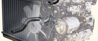
During its operation, the engine heats up to a very high temperature threshold. This circumstance is very fraught with problems for all surrounding elements. This is also dangerous for those people who are in the cabin. That is why a special complex was developed in order to “pacify” elements ready to boil.
This allows you not to worry that something will “boil” during operation. The latest VAZ 21214 models are equipped with a four-cylinder 8-valve gasoline engine system. It was here that the fuel injection system found its application. This is reflected in this set.
Engine cooling system
The cooling system is liquid, closed type, with forced circulation.
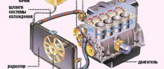
The tightness of the system is ensured by valves in the expansion tank plug. The inlet valve is normally open (the gap between it and the rubber gasket is 0.5–1.1 mm) - in this case, the system communicates with the expansion tank. When the engine heats up, the liquid expands and is forced into the tank; when it cools, it returns back. The inlet valve closes when there is a sharp increase in pressure in the system (boiling liquid), while the outlet valve is also closed. It opens when the pressure in the system reaches approximately 0.5 kgf/cm2, which increases the boiling point of the liquid and reduces its losses. The thermal operating conditions of the engine are maintained by a thermostat and a radiator fan. On a carburetor engine, the fan is mechanically driven and mounted on the coolant pump pulley. On an engine equipped with an injection system, two electric fans are installed in front of the radiator and are activated by command from the electronic engine control unit. Carburetor engine cooling system
Injection engine cooling system
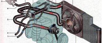
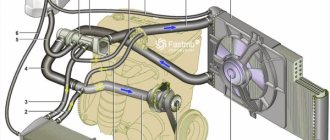
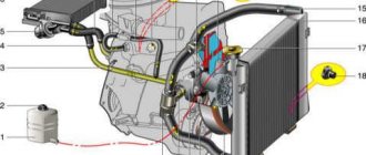
1 – expansion tank; 2 – expansion tank plug; 3 – pipe for draining fluid from the heater radiator; 4 – hose for draining fluid from the heater radiator; 5 – heater tap; 6 – heater radiator; 7 – hose for supplying fluid to the heater radiator; 8 – hose for supplying fluid to the carburetor heating block; 9 – hose for draining fluid from the carburetor heating unit; 10 – thermal vacuum switch of the recirculation valve; 11 – thermostat bypass hose; 12 – coolant pump cover; 13 – fan impeller; 14 – coolant temperature sensor for the instrument cluster; 15 – radiator supply hose;
16 – radiator; 17 – radiator cap; 18 – radiator drain plug; 19 – fan casing; 20 – radiator outlet hose; 21 – coolant pump drive belt; 22 – coolant pump housing; 23 – hose for supplying coolant to the pump; 24 – thermostat; 25 – coolant supply hose to the throttle body; 26 – coolant drain hose from the throttle body; 27 – coolant temperature sensor for the injection system; 28 – electric fan impeller; 29 – electric motor; 30 – electric fan casing.
The coolant pump is a vane, centrifugal type, driven from the crankshaft pulley by a V-belt. The pump housing is aluminum. The roller rotates in a double-row bearing with a lifetime supply of lubricant. The outer ring of the bearing is locked with a screw. A pulley hub is pressed onto the front end of the roller, and a plastic impeller is pressed onto the rear end. For the correct position of the pump pulley groove, the distance from the mating surface of the pump cover to the outer end of the hub must be 84.4 ± 0.1 mm. When installing the cover with the gasket, check the gap of 0.9–1.3 mm between the impeller blades and the pump housing. To do this, you can use plasticine rollers: they are placed on equidistant impeller blades, a cover is installed, the nuts securing it are tightened, then the cover is removed and the remaining thickness of the plasticine is measured - it is equal to the gap.
Axial and radial play in the pump bearing that can be felt by hand is not allowed. If the bearing or self-pressing seal of the pump fails, it is recommended to replace the pump cover complete with the roller and impeller.
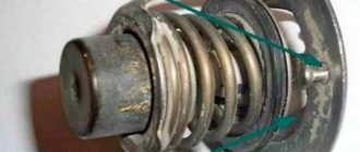
The redistribution of liquid flows is controlled by a thermostat with a solid heat-sensitive element. On a cold engine, the thermostat valve closes the pipe leading to the radiator, and the liquid circulates only in a small circle (through the thermostat bypass pipe), bypassing the radiator. The small circle includes the heater radiator, intake manifold, carburetor heating unit (on engine 21213) or throttle assembly (on engine 21214). At a temperature of 78–85°C, the valve begins to move, opening the main pipe; in this case, part of the liquid circulates in a large circle through the radiator. At a temperature of about 90°C, the main valve opens completely, and the bypass valve closes, and all the liquid circulates through the engine radiator. The main valve stroke must be at least 6.0 mm.
You can evaluate the serviceability of the thermostat by heating the lower radiator pipe: it should be cold until the liquid temperature (according to the indicator) reaches 80–85°C, and hot when it rises to 85–90°C. The thermostat is beyond repair. In case of malfunction, loss of tightness, or deformation of the pipes, it is replaced.
The radiator consists of two vertical plastic tanks (the left one has a baffle) and two horizontal rows of round aluminum tubes with pressed-on cooling plates. To increase cooling efficiency, the plates are stamped with a notch. The tubes are connected to the tanks through a rubber gasket. The liquid is supplied through the upper pipe and discharged through the lower. There is a coolant drain plug at the bottom of the left reservoir.
For better radiator airflow, casings are designed to direct air flow from the fan(s).
On the 21213 engine, the main fan shroud consists of two halves (lower and upper), the lower half has a rubber seal on the radiator side. An additional guide casing is installed in front of the radiator. On the 21214 engine, electric fans rotate in a casing in front of the radiator.
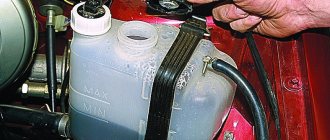
The expansion tank is made of translucent polyethylene, which allows you to visually monitor the fluid level (3–5 cm above the “MIN” mark on a cold engine).
To monitor the coolant temperature, a sensor is screwed into the engine cylinder head and is connected to a temperature gauge on the dashboard. An additional temperature sensor is installed in the exhaust pipe of the 21214 engine, which provides information to the electronic engine control unit (see here).
The heating system is described here.
Video
How to properly replace coolant?
You need to start replacing the coolant on a VAZ 21214 by choosing a suitable refrigerant . You can choose the original coolant, or choose one of the available analogues. The original antifreeze has been produced since 2014. Name of liquid: Antifreeze LADA G12. Designed for use at temperatures down to -40 degrees Celsius. Product number: 88888-2000010-82.
When choosing a liquid, you need to pay attention to its labeling. For Niva (including VAZ 21214) you need a coolant with an operating temperature no higher than -40 degrees. The following liquids are suitable:
- Antifreeze of domestic production. You need to take a high-quality coolant. The marking “Antifreeze -40” means a freezing temperature of -40 degrees. For regions in the Arctic Circle, antifreeze labeled “Antifreeze -65” is suitable. An example of a suitable liquid: Felix antifreeze.
- Standard antifreeze. Both domestic and foreign coolants are suitable. Here again the minimum operating temperature is checked. It is equal to -40 degrees Celsius. Example: products from G-Energy or SINTEC. Felix Carbox antifreeze will also work.
It’s also worth considering that the original LADA antifreeze is sold in an already diluted form. But when purchasing concentrate from other companies, it should be diluted. The exact proportions are written on the coolant packaging.
Tools and materials for work
Then you need to figure out the tools and materials.
The list of tools for replacing coolant in a VAZ 21214 looks like this:
- Container for draining used antifreeze. Volume - 12 liters.
- Thick and durable coolant drain hose.
- Wrenches for 13 and 15. It is recommended to have box, open-end and ratchet wrenches of the appropriate size in the kit.
- Funnel for filling the radiator and expansion tank.
- Round nose pliers for removing the receiver hose.
- Cooling system flushing products.
- Antifreeze to replace. The Niva’s cooling system holds 10.7 liters. Therefore, 11 liters are purchased, with a small reserve in case of leaks.
- WD-40 for cleaning screws.
Vehicle preparation and safety precautions during operation
The next step is to prepare the car for replacing the coolant. It goes like this:
- The Niva is driven onto an overpass or placed above an inspection hole.
- The car is firmly secured: it is put into speed and the hand brake is applied. It is recommended to install wheel stoppers.
- The motor is allowed to cool. Working with hot antifreeze is inconvenient and hazardous to health.
It is also worth remembering safety precautions . Here are a number of simple but important recommendations:
- Antifreeze should not come into contact with eyes or respiratory tract. This liquid is toxic and is a strong poison.
- Work should be done in a ventilated area. Coolant fumes are not beneficial to health.
- You should wear comfortable, loose clothing. The work uniform does not restrict movement and does not interfere with the process of replacing antifreeze.
- Coolant must not get into the fuel. This will have a very negative effect on the operation of the motor.
Now you can proceed to the actual replacement procedure.
How does cooling work on the VAZ 2121 Niva?
The lifespan of a Niva SUV engine largely depends on how efficiently the VAZ-2121 cooling works. After all, overheating is the first enemy of the power unit, leading to expensive repairs.
This is why the serviceability of the components and elements of the cooling circuit is so important. In order to be able to service them and identify malfunctions, you need to understand what the circuit consists of and how the Niva’s cooling functions.
Operating principle of the coolant temperature sensor
The thermistor, which is located in the internal part of the product, is characterized as an electronic device with the so-called. “negative indicator of temperature regime”, i.e. When heated, the resistance of the device decreases and, accordingly, when cooled, it increases.
An increased temperature range of up to 130°C reduces the resistance of the product within 70 Ohm +2%, and a lower limit at a temperature of −40°C increases the resistance to 107 KOhm ±2%.
The detector-controller passes a voltage of 5 V to the temperature sensor through a constant resistance located inside it. The controller determines the temperature values of the coolant liquid by the potential difference across a temperature sensor with a variable resistance. On a cooled motor the voltage is high, and on a warm unit it is low.
When operating a device such as a VAZ 2110 injector temperature sensor, it should be remembered that the temperature regime of the coolant has a significant impact on many technical characteristics that are subject to control by the controller.
Vehicle cooling network design
The cooling system of the VAZ Niva is quite effective and has undergone virtually no changes since its creation. It includes the following units and elements:
Temperature control in the Niva engine cooling network is carried out in different ways. In the carburetor model VAZ-21213, a sensor is built into the cylinder head, connected to the temperature indicator on the dashboard. On the VAZ-21214 model, where the fuel is supplied by an injector, there is a second sensor mounted in the pipe on the cylinder head. It is connected to a controller that prepares the fuel mixture depending on the heating of the power unit and turns on the fans.
There are 2 more differences in the cooling design of engines with a carburetor and an injector:
- on cars with direct fuel injection, 2 electric fans are installed on the radiator instead of 1 mechanical;
- The heating pipes for the lower part of the carburetor in model 21214 provide heating for the throttle body.
In VAZ-2131 Chevrolet Niva cars, the cooling system is generally similar to a regular Niva with an injector. The VAZ-2131 heater radiator is not equipped with a tap, which is why antifreeze flows through it all year round.
Possible problems and their causes
Like any vehicle system, the cooling circuit must be regularly monitored and worn parts replaced. The first indicator of possible problems will be the level of coolant in the expansion tank. The main breakdowns of the cooling systems of VAZ Niva models:
- Maximum engine heating with cold main radiator pipes means the thermostat is broken. The part cannot be repaired, only replaced.
- Electric fans in injection systems turn on uncontrollably or do not start at all. This is an indicator of a breakdown of the sensor that transmits data to the controller.
- A faulty sensor on the cylinder head causes incorrect data on the control panel or its complete absence.
- A constant decrease in antifreeze level indicates a leak somewhere in the circuit.
Operating principle
The Niva's cooling circuit operates under pressure, since in normal mode it does not communicate with the atmosphere. The coolant is antifreeze with a freezing point of -40 °C. It is a solution of water with ethylene glycol, the amount to fill the system is 10.7 liters. It also boils at an elevated temperature, +110 °C.
The key element in the operation of the system is the thermostatic valve, which distributes fluid flows depending on the heating of the engine. Inside the thermostat there is a damper controlled by a temperature-sensitive element. When heated, it moves the damper, opening another path for the flow. In general, the scheme works according to the following algorithm:
In the summer and transition period in VAZ-21213 and 21214 cars, the passage of coolant through the heater radiator is limited by a tap. There is no such tap on the Chevrolet Niva; the heating is turned off by redirecting the air flow past the heat exchanger.
Main fuse box
Scheme
p, blockquote 12,0,0,0,0 —>
p, blockquote 13,0,0,0,0 —>
Purpose
p, blockquote 14,0,0,0,0 —>
| 1 | 16A Heater fan electric motor Relay (winding) for headlight wipers and electric motors for headlight wipers in all wipe positions except the initial Relay (winding) for turning on the rear window heating Electric motors for the rear window cleaner and washer Electric motor for the windshield washer |
| 1* | 16A Lamps Horns Socket Lighter Brake light |
| 2 | 8A Relay and electric motor of the windshield wiper Turn signal lamps and relay-interrupter for direction indicators and hazard warning lights (in turn signal mode) Turn signal indicator lamp Tail lights (reversing light lamps) Generator excitation winding (when starting the engine) Differential lock activation indicator lamp in the transfer case Indicator lamp for turning on the parking brake Indicator lamp for the emergency condition of the service brake system Indicator lamp for insufficient oil pressure Fluid temperature indicator in the engine cooling system Fuel level indicator with a warning lamp for fuel reserve Indicator lamp for battery charge Indicator lamp for closing the carburetor air damper Tachometer Electric heater motor Relay headlight cleaners and washer (with the headlight cleaner and washer switch button not pressed) Headlight wiper electric motors in all brush positions except the initial one* |
| 3 | 8A Left headlight (high beam lamp) Indicator lamp for turning on the high beam headlights |
| 4 | 8A Right headlight (high beam lamp) |
| 5 | 8A Left headlight (low beam) |
| 6 | 8A Right headlight (low beam) |
| 7 | 8A Left front light (side light) Right rear light (side light) License plate lights Indicator lamp for turning on side lights |
| 8 | 8A Right front light (side light) Left rear light (side light) Instrument lighting lamp Heater control lever backlighting lamp Cigarette lighter lighting lamp Illumination lamps for switches and switches |
| 9 | 16A Direction indicators and relay-breaker for direction indicators and hazard warning lights Rear window heating element and relay (contacts) for its activation |
| 9* | 8A Warning lamp and oil pressure gauge Coolant temperature gauge Fuel level gauge with reserve warning lamp Parking brake warning lamp Brake fluid level warning lamp Turn indicators and corresponding warning lamp Carburetor choke control warning lamp Battery charge warning lamp Carburetor shut-off valve Tachometer Rear lights (reverse light) Differential lock warning lamp Turn signal relay interrupter Heated rear window (control circuit) |
| 10 | 16A Sound signal Cartridge for connecting a portable lamp Interior lamps Tail lights (brake lamps) |
| 10* | 8A Voltage regulator Generator excitation winding |
| 11 | 8A Turn signal lamps and relay-breaker for turn signals and hazard warning lights (in hazard warning mode) Rear fog lamp |
| 12 | 8A Daytime running light relay, daytime running light lamps |
| 12* | 8A Headlight cleaner and washer relay (with the headlight cleaner and washer switch button pressed) Headlight washer electric motor Headlight cleaner electric motors at the moment of start-up and when the brushes pass the initial position |
| 13 | 8A Rear lights (fog light lamps) Electric motors for headlight cleaners at the time of start-up and when the brushes pass the initial position Relays (contacts) for headlight cleaners Electric motor for headlight washers |
| 14 | 16A Cigarette lighter |
| 15 | 16A Backup Heated rear window (power circuit) |
| 16* | 8A Hazard warning switch and direction indicators in hazard warning mode Rear window wiper and washer |
Fuse number 14 or number 1 at 16A is responsible for the operation of the cigarette lighter, depending on the year of manufacture.
Possible faults
To avoid problems with engine overheating, it is necessary to monitor and maintain the Niva’s cooling system.
You should check the antifreeze level in the expansion tank more often. Due to the reliability of cooling, there are not many malfunctions in it:
- When the car heats up to maximum in any weather, and the main radiator pipes are cold, the thermostat has broken. The element is not repaired, only changed.
- Electric fans turn on at random, including when the engine is cold, but if they overheat, they may not start. This means that the sensor transmitting temperature data to the controller has failed and must be replaced.
- When the indicator on the panel gives inaccurate data or does not show the temperature, you need to change the second sensor located in the cylinder head.
- The fluid level in the tank is constantly decreasing. It is necessary to look for and eliminate leaks in the pipes or in one of the radiators.
It is important to periodically check for play in the water pump shaft. Its appearance indicates wear of the bearing; it is necessary to change the pump as soon as possible.
Main element device
As for the cooling radiator, it is impossible to imagine the operation of the engine as a whole without it. It is represented by these components:
- upper and lower tanks;
- core;
- fastening parts.
Its main purpose is to cool the mixture coming from the water jacket to the required temperature standard. Good thermal conductivity is facilitated by the fact that it is usually made of brass. The core contains transverse plates. Once here, the reagent is divided into many streams - this allows you to get a more effective result.
The principle of operation goes like this:
- The pump constantly “moves” liquid into the VAZ 21214.
- The system operates in such a way that water circulates in a circle, washing the heated walls of the blocks and cylinder.
- In this case, engine overheating can be avoided, and heat will be guaranteed to be removed from important parts.
- Then the mixture goes through the radiator, and after that it is released into the environment.
- Thus, the cyclicity is completed - now the cooled liquid will have to repeat it again for the VAZ 21214.
Engine cooling system for VAZ NIVA VAZ21213 and VAZ-21214
1. Coolant temperature sensor for the fuel injection system. 2. Radiator supply hose. 3. Tank cap. 4. Expansion tank. 5. Radiator cap. 6. Hose from the radiator to the expansion tank. 7. Cooling jacket. 8. Filler neck. 9. Plug inlet valve. 10. Exhaust (steam) valve of the plug. 11. Left radiator tank. 12. Radiator core. 13. Right radiator tank. 14. Fan impeller. 15. Turbulizer. 16. Rubber radiator support. 17. Fan shroud. 18. Fan belt. 19. Radiator outlet hose. 20. Coolant pump. 21. Coolant supply hose to the pump. 22. Thermostat. 23. Thermostat bypass hose. 24. Fluid drain pipe from the heater radiator. 25. Fluid drain hose from the carburetor heating unit. 26. Fluid supply hose to the carburetor heating unit. 27. Fluid drainage hose from the heater radiator. 28. Fluid supply hose to the heater radiator. 29. Rubber insert. 30. Inlet pipe (from the radiator). 31. Main valve. 32. Thermostat housing. 33. Bypass valve. 34. Overflow hose connection. 35. Coolant supply pipe to the pump. 36. Thermostat cover. 37. Piston. 38. Pump cover. 39. Thrust seal ring of the oil seal. 40. Oil seal. 41. Pump roller bearing. 42. Fan pulley hub. 43. Locking screw. 44. Pump roller. 45. Pump housing. 46. Pump impeller. 47. Intake pipe. I. Thermostat operation diagram. A. Liquid temperature is less than 80oC. B. Liquid temperature is from 80 to 94oC. C. Liquid temperature is more than 94oC.
The engine cooling system is liquid, closed, with forced circulation of coolant. The system is filled with Tosol D-40 coolant and an aqueous solution of Tosol-A antifreeze (concentrated ethylene glycol with anti-corrosion and anti-foaming additives with a density of 1.078-1.085 g/cm2).
The cooling system is filled with 10.7 liters, including the interior heating system. The fluid level in the expansion tank should be 3-4 cm above the “MIN” mark, checked on a cold engine (at 15-20°C).
To monitor the coolant temperature, there is a sensor installed in the cylinder head and a pointer on the instrument panel.
The cooling system includes: coolant pump 20, cooling jackets for the block and cylinder head, thermostat 22, fan, radiator, expansion tank 4, pipelines and hoses. When the engine is running, liquid heated in the cooling jackets flows through the outlet pipe through hoses 2 and 23 into the radiator or thermostat, depending on the position of the thermostat valves. Next, the cooled liquid is sucked in by pump 20 and supplied again to the cooling jackets. The coolant pump is a centrifugal type, driven from the crankshaft pulley by a V-belt that drives the generator.
The pump housing 45 and cover 38 are cast from aluminum alloy. In the cover, in bearing 41, which is locked with a screw 43, a roller 44 is installed. Bearing 41 is double-row, non-separable, without an inner race. The bearing is filled with Litol-24 grease during assembly and is not subsequently lubricated.
A cast iron impeller 46 is pressed onto the roller on one side, and the hub 42 of the pump drive pulley is pressed onto the other side. The end of the impeller in contact with the sealing ring is hardened with high frequency currents to a depth of 3 mm. The sealing ring is pressed against the impeller by the oil seal spring through a rubber collar. Oil seal 40 is non-separable and consists of an outer brass ring, a rubber cuff and a spring. The oil seal is pressed into the pump cover 38. The pump is driven by a V-belt 18.
The fan is a six-blade impeller 14 made of plastic, which is bolted to the hub 42 of the pump drive pulley. The fan blades have a variable radius installation angle and, to reduce noise, a variable pitch along the hub. For better operating efficiency, the fan is located in a casing 17, which is bolted to the radiator brackets.
Radiator and expansion tank. The radiator is collapsible, with plastic tanks 11 and 13, with two rows of aluminum horizontal tubes and aluminum cooling plates. The radiator core 12 is sealed with the tanks using rubber gaskets. For better cooling efficiency of the liquid, turbulators 15 are installed in the tubes. The radiator is mounted on rubber supports 16 and bolted to the front of the body. The filler neck of the radiator is closed with a plug 5 and connected by a hose to a translucent plastic expansion tank 4. The radiator plug has inlet 9 and outlet 10 (steam) valves, through which the radiator is connected to the expansion tank. The inlet valve 9 is not pressed against the gasket (the gap is 0.5-1.1 mm) and allows the inlet and outlet of coolant into the expansion tank when the engine is heating and cooling.
When the liquid boils or a sharp increase in temperature due to low throughput, the inlet valve does not have time to release liquid into the expansion tank and closes, disconnecting the cooling system from the expansion tank. When the pressure increases when heated to 50 kPa, the outlet valve 10 opens, and part of the coolant is transferred into the expansion tank. Thermostat and cooling system operation. The cooling system thermostat accelerates engine warm-up and maintains the required thermal operating conditions of the engine. At optimal thermal conditions, the coolant temperature should be in the range of 85-95°C. The temperature values maintained by the thermostat are indicated on its bottom.
Thermostat 22 consists of a body and a cover, which are rolled together with the seat of the main valve 31. The thermostat has three pipes: an inlet pipe for inlet of coolant from the radiator, a pipe bypass hose 23 for bypassing liquid from the cylinder head to the thermostat, and a pipe for supplying coolant to the pump. 20.
The main valve 31 is installed on the thermoelement glass, in which a rubber insert 29 is rolled. The rubber insert contains a polished steel piston mounted on a stationary holder. Between the walls and the rubber insert there is a heat-sensitive solid filler. The main valve 31 is pressed against the seat by a spring. Two posts are attached to the valve, on which a bypass valve 33 is installed, pressed by a spring.
The thermostat, depending on the temperature of the coolant, automatically turns on or off the radiator of the cooling system and bypasses the liquid through the radiator or bypassing it
On a cold engine, when the coolant temperature is below 80°C, the main valve is closed and the bypass valve is open. In this case, the liquid circulates through the hose 23 through the bypass valve 33 into the pump 20, bypassing the radiator (in a small circle). This ensures quick warm-up of the engine.
If the liquid temperature rises above 94 ° C, the solid filler of the thermostat expands, compresses the rubber insert 29 and pushes out the piston, moving the main valve 31 until it is completely open. The bypass valve 33 closes completely. In this case, the liquid circulates in a large circle: from the cooling jackets through hose 2 to the radiator and then through hose 19 through the main thermostat valve it enters pump 20, which is again sent to the engine cooling jackets.
Within temperatures of 80-94°C, the thermostat valves are in intermediate positions, and the coolant circulates in both small and large circles. The opening value of the main valve ensures gradual mixing of liquid cooled in the radiator, thereby achieving the best thermal operating conditions of the engine.
What to do if liquid leaks? What kind of breakdowns happen?
Often problems in the cooling system are caused by breakdowns and leaks. And the condition of the antifreeze does not play any role here. Here is a list of possible malfunctions and how to fix them:
- Thermostat failure. This part is responsible for the connection between the external and internal circuits of the cooling system. In normal condition, it remains cold at operating temperatures below 80-85 degrees. If the liquid heats up more, the thermostat becomes hot. If there is a malfunction, the thermostat no longer heats up, or is constantly hot. And then it has to be changed. It is worth remembering that this part cannot be repaired, only replaced.
- Pump breakdowns. Possible problems: broken impeller blades, cracks in the housing, failure of seals. In case of leaks, it is worth checking whether the problem is in the pump or in the hoses.
- Problems with the cylinder block. If cracks appear or there is a manufacturing defect, you will have to turn to professionals. But sometimes problems arise due to a rotten block cover gasket. This is usually due to the use of ordinary water in the cooling system. Diagnosis is simple: dense, white or bluish smoke constantly comes out of the exhaust pipe. Here the cylinder block gasket is replaced.
- Development of the service life of system hoses. The solution is simple - replacing the hoses. It is done by hand. Tools: pliers and a screwdriver for removing clamps. Old hoses are removed and thrown away, new ones are installed in their place.
- Problems with the expansion tank. Cracks appear on it, and the container has to be replaced. The procedure is simple: the screws on the tank fastenings are unscrewed, the old container is removed, and a new one is installed.
- Problem with radiator fans. There are two of them. One or both can fail at once. Repairs can only be made by an experienced electrician.
- Radiator leaks. Corrected by repair or replacement of the part. But you won’t be able to fix this on your own; you need the help of a professional.
The system should be checked for malfunctions before replacing the fluid. After all, when repairing the cooling system, all the antifreeze is drained. Therefore, it is worth filling in a new one after the repair.
How to change antifreeze on a VAZ 21214 Niva
The Niva SUV, in all modifications, is very popular in Russian spaces. This is due to good maintainability, low price and excellent maneuverability. To ensure reliable operation, you should undergo all maintenance on time, in particular, replace the coolant.
The liquid system with forced circulation of the VAZ 21214 car is designed for effective heat removal. It fully copes with its task, you just need to keep it in good condition.
Replacing antifreeze VAZ 21214
Replacing the coolant is a regulated maintenance procedure, which is prescribed in the operating instructions. There is nothing complicated about it if you clearly and carefully follow the described action plan.
Suitable for Niva cars:
Coolant drain
Before starting the draining procedure, you should prepare tools, containers for used antifreeze, as well as new liquids for subsequent refilling. If protection is installed under the engine, it can also be removed for convenience.
Next, we perform the procedure for draining the liquid from the VAZ 21214 (Niva):
- turn the temperature regulator in the cabin to the maximum position to the right (Fig. 1);
Flushing the cooling system
If there are deposits in the drained liquid or there is a transition from antifreeze to antifreeze, the system should be flushed. To do this you need to do the following:
- Flush the system with plain water through the expansion tank of the VAZ 21214. The plugs must be open;
- tighten the drain plug and bolt;
- fill the system with a flushing agent (you can use Liqui Moly Kuhlerreiniger or Lavr cooling system flush) with distilled water (6-7 liters);
- start the engine. Warm up to 90 degrees;
- leave it idling for 5-10 minutes, depending on the contamination of the system;
- muffle it. Allow the engine to cool to approximately 60 degrees;
- drain the flush using the same steps as removing the old fluid;
- tighten both plugs;
- fill with distilled water to rinse the cooling system;
- start the car and warm up to 90 degrees;
- turn off and let cool to 60 degrees, drain;
- repeat steps 8, 9, 10 and 11 if necessary.
Filling antifreeze into Niva 21214, 21213 without air locks
To fill new fluid into the cooling system, you can use the instructions described in the book on car repair and operation. But when doing this, motorists very often end up with air jams.
So, let's start filling it correctly:
- before filling, unscrew the hoses supplying antifreeze to the throttle valve heating unit and lift them slightly up (Fig. 1);
The filling of the liquid is completed, all that remains is to wipe off the spilled antifreeze and wait for the engine to cool. With the car now cooled down, check the level in the expansion tank again and top up if necessary.
Carburetor Features
When modernizing the Niva in 1994, it was decided to install a Solex carburetor on it.
Before this, a unit called Ozone was used. Which one is better? This question interests many owners. Ozone is equipped with an old style breaker. In addition, it does not have a vacuum corrector. Solex does not have a microswitch for the economizer. This negatively affects the purity of the exhaust, and also partly on fuel consumption. Both carburetors have both their advantages and disadvantages. However, VAZ engineers opt for Solex, as a more modern model. In turn, many owners of cars with this carburetor often complain about its incorrect operation. Experts explain that this is caused primarily by the use of low quality fuel. In addition, troubles can arise for those who rarely change the fuel or air filter, and also do not clean the carburetor of oil soot entering through the ventilation system. Some owners of old Niva cars equipped with Ozone decided to install Solex instead. And they don’t regret it.
Adjusting the carburetor VAZ 21213
This procedure may be necessary when jerks or dips appear during movement. In addition, adjustment is needed if the car has an unstable idle. It is advisable to know what fuel consumption accompanies these symptoms. If you have no desire to go to a car repair shop, you can adjust the carburetor of the VAZ 21213 and eliminate the causes of incorrect operation with your own hands. It's not much more difficult than adjustment.
First you need to remove the air filter. But before this, the engine must run for at least a few minutes. You can now disconnect the fuel supply hose. To remove the carburetor cover you will need to unscrew five bolts. After removing the lid, place it on a flat surface. Now we take a caliper and measure the distance from the edge of the body of the float chambers to the level of the fuel in them. Normally it should be 25.5 mm. In cases of non-compliance with the standard, the tongue of the float bracket should be bent. To achieve a positive result, this will most likely have to be done more than once. After each bending, we check the distance to the fuel and adjust our actions. Having achieved success, we put everything back together.
Now you need to adjust the engine idle speed. To do this, fully tighten the mixture quality screw. Then unscrew it 4 turns. We start the engine, turn on the high beam lamps and the fan. The choke handle must be recessed. Using the screw that regulates the amount of mixture, we bring the number of revolutions to 800 per minute. After this, we use the quality screw to achieve maximum speed. Now use the quantity screw to reduce the speed to 900 per minute. We go again to the quality screw, and with it we reduce the speed to 800. We turn the quality screw until the engine operation becomes unstable. As soon as this happens, unscrew the quality screw 1 turn. And finally, use the quantity screw to achieve the required speed level. Which one is needed? For summer from 800 to 900, for winter from 900 to 1000 rpm.
Replacement frequency, how much and what kind of fluid is needed
According to the manufacturer's recommendation, it is necessary to replace antifreeze or antifreeze on VAZ-21214 cars every 3 years or after a mileage of 60 thousand kilometers. If the car is used in more severe conditions, then it is advisable to replace it more often - every 30-40 thousand kilometers.
In addition to the recommended coolant change intervals, there are other reasons why it is necessary to change the fluid in a car's cooling system:
- loss of coolant properties. You can check the quality of the antifreeze used using a test strip, which is sold in the same places where the liquid itself is sold. Place the strip in the expansion tank, then pull it out. The strip comes with a color scale, according to which you can understand how much longer the car can be used before replacing the coolant;
- change in color of the coolant to tan or red. This means that rust has appeared in it;
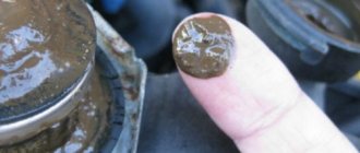
- the appearance of sediments, flakes and dense formations in the liquid.
The coolant for the VAZ 21214 Niva injector should have a freezing point no higher than -40 degrees. Typically, the manufacturer fills in TOSOL TS-40 (manufacturer in Dzerzhinsk). When replacing antifreeze, it can be replaced with antifreeze with G12 approval; it is safer for the entire cooling system. You can also use original Lada G12 antifreeze, which is suitable for all cars of this manufacturer.
Antifreeze volume table
| Model Niva | Engine capacity | Antifreeze volume | Original/recommended fluid |
| VAZ 21214 | 1.7 | 10.7 | Lada G12, TOSOL TS-40 |
| VAZ 21213 | 1.6-1.7 | 10.7 | |
| VAZ 2121 | 1.4-1.8 | 10.6 | |
| VAZ 2131 | 1.7 | 10.7 |
The main elements of the system and what are the benefits of silicone pipes
The details of the system are presented in the diagram above, these include:
- air cooling radiator (art. 2123-1301012);
- casing with fans (art. 2123-1300025-01);
- temperature sensor (art. 2101-3808600-02 and 2112-3851010);
- water pump (art. 2123-1307010);
- thermostat (art. 2123-1306010);
- pump (art. 21230-1307011-82).
All elements of the cooling system are connected to each other through various hoses and pipes, which in most cases are made of rubber or polymers with similar properties.
As a reasonable alternative to rubber hoses, car enthusiasts increasingly prefer silicone analogues, which are significantly more expensive. The main reason for this is that silicone does not “tan” in the cold and does not crack. This prevents coolant from leaking out of the system, which greatly affects its performance. Complete set of Chevrolet Niva cooling system pipes:
- Upper radiator hose - 1 piece;
- Lower radiator hose - 1 piece;
- Thermostat and water pump pipe 1 piece;
- Heater radiator supply hose;
- Heater radiator outlet hose.
The strength of the silicone itself largely depends on the thickness of the tube walls, as well as the presence of special reinforcement. Parts made from this material, made specifically for cooling systems, are often characterized by double reinforcement, which makes their design much stronger and more durable.
If you believe the reviews of the Shniva owners themselves, then all the additional costs of replacing rubber cooling pipes with silicone ones are completely justified. This is especially true if the car is operated in harsh northern conditions.
It should also be noted that in most cases the connections are clamped with spring clamps and only in rare cases are screw clamps used. Another undoubted advantage of silicone is the fact that it resists the effects of gasoline well without changing its physical properties.
Replacing the heater valve VAZ 21214 Niva without draining antifreeze
Niva cars sometimes have problems associated with the failure of some parts of the cooling system, such as a thermostat or pump. If they break down, they are replaced as an assembly, fortunately they are not expensive. Also a common problem are leaking hoses or a cracked expansion tank, which also needs to be replaced.
But there is another problem with the VAZ 21214, a leaking heater valve. Because of this, there may be a smell of antifreeze in the cabin, wet floor mats on the front passenger side, or the heater may not work.
There are several ways to replace a faulty faucet:
- complete draining of antifreeze from the system;
- clamp the stove pipes with special clamps;
- Place your Niva on a slope, with the hood down.
But there is another option that is more clear and simple. To do this, you need to disconnect the pipes going to the stove under the hood, point them upward and fix them in this position. The next step is to remove the stove itself:
- unscrew the console;
- disconnect the latches securing the stove;
- there is no need to disconnect the buttons;
- move the radiator assembly, along with the tap and pipes, towards the driver;
- we take out the entire structure through the space between the steering wheel and pedals;
- That's it, you can change the tap itself.
After replacement, reassemble in reverse order. As you can see, this operation is quite simple, and antifreeze will not leak into the cabin. And the procedure takes only 40 minutes, even for an unprepared person.
How to fix problems
Now let's talk about eliminating these faults according to the list presented.
- Coolant cannot disappear with the wave of a magic wand; it does not evaporate under the influence of temperature. Therefore, you need to check all pipes, hoses, clamps, radiator and other components. There is bound to be damage somewhere causing a leak.
- If in winter you have to stand still for a long time waiting for the engine to warm up, try insulating the engine compartment. There are many ways to do this - from the classic “sheep coat” for the engine, to using simple cardboard in front of the radiator in winter, or using special insulation. Be sure to ensure that your insulation does not touch the generator belt.
- In the event of detonation, we can only sympathize with the car, since its owner completely ignored all the signals from the car that the CO was in a faulty state. If the simplest repair measures give a positive result, consider yourself very lucky. If not, then engine repair cannot be avoided. And these are completely different amounts of money.
- When the sensor needle is in the red zone, immediately take appropriate measures. Turn off the engine to prevent excessive overheating from leading to even worse consequences. Raise the hood and check for fluid in the reservoir. Just don't open it, it's very hot in there. With a timely reaction, you can avoid boiling and whistling from under the hood. But it’s better not to drive to the service station on your own. Call a tow truck.
- Situations where engine head gaskets break are not uncommon. But we don’t want anyone to encounter them. Such a breakdown indicates that you must begin a full engine repair. On your own or at a car service - decide for yourself.
