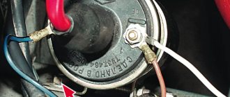
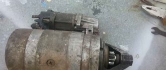
As you know, in order to start a car engine, it is necessary to ignite the mixture of fuel and air in the combustion chambers of the cylinders. To do this, several conditions must operate synchronously, one of which is the rotation of the crankshaft. To spin it up at least at minimum speed, a converter of electrical energy into mechanical energy is used. This device is called the “starter”.
The design of the VAZ 2106 starter and the principle of its operation
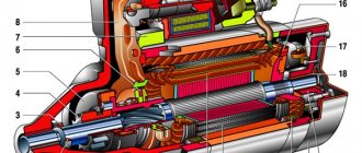
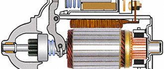
They were not equipped with a starter with index 35.3708, and the very first models ST-221 were gear type. Export models were equipped with German-made devices. The diagram of this, in fact, power electric motor is shown in the photo.
- Drive shaft.
- Cover sleeve.
- Restrictor ring.
- Gear with overrunning clutch ring.
- Overrunning clutch roller.
- Support with liner.
- Gear axis.
- Pad.
- Drive arm bracket.
- Lever arm.
- Front cover.
- Traction relay rotor.
- Stator.
- Retractor stator.
- Traction relay.
- Relay rod.
- Relay core.
- Contact plate.
- Lid.
- Bolts for contacts.
- Brush assembly output.
- Brace.
- Brush holder.
- Plus brush.
- Rotor shaft.
- Hairpin for tie.
- Back cover.
- Collector.
- Aluminium case.
- Magnet with constant field.
- Rotor core.
- Rotor shaft support.
- Planetary gear.
- Drive gear.
- Driven.
- Gear with teeth inside.
- Retraction ring.
- Hub.
The rated power is 1.3 kW, current is 500 Ampere and 550 A for ST-221 and 35.3708, respectively.
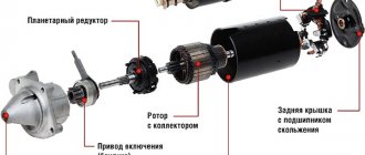
The starter is an aluminum housing that contains a copper stator winding, a rotor, two covers (front and rear) and an electromagnetic type relay on top. The body is connected to the covers using studs. The stator has three serial winding poles (connected in series with the rotor winding) and one shunt-type winding, which is connected in parallel.
The armature is a core on the shaft, a copper winding and a platform for graphite brushes, called a commutator. The clutch is designed to transmit torque from the Bendix to the flywheel, then the crankshaft begins to rotate and the engine starts. After starting, it also serves to break the connection between the flywheel and the bendix. A traction relay consists of two windings and a core.
Set 1 Starter Relay Magnetic Starter Relay Part Number: 68N 81940 00 00 | |
Description:
Replaces Yamaha Part Number: 68N-81940-00-00 100% Brand new, good working condition High quality material, efficient and durable, competitively priced Reliable replacement electrical parts Easy to install, directly replaces the old one
Specification:
Fits many 2002-2017 Yamaha FX and WaveRunner models: FX140, FX140 Cruiser, GP800R, GP1200, GP1300R, Superjet, SUV1200 Many, XL700, XLT800 and XLT1200 2002-0007 Fits 2005 Yamaha Jet Boat Models: AR210, AR23 0, LS2000, LX210, LX2000, SR230 and SX230
The kit includes:
1 set starter relay
Starter operating principle
When the ignition key is turned to the “start” position, power is supplied to the traction relay, after which the core is pulled inward. When retracted by the fork, it moves the gear drive to the teeth of the engine flywheel, resulting in the starter engaging with the power plant. In parallel with this core, the contacts of the traction relay are closed, which in turn transmit power voltage to the stator windings.
A car starter is an electric motor designed for short-term operation. When starting the power unit, it is not recommended to hold the key in the ignition switch in the “start” position for more than 15 seconds. Between attempts to start the engine, the starter operation should be interrupted for 30–40 seconds (in winter, at least a minute). Operating the device for a long time will lead to overheating of the rotor and stator, as a result of which the varnish of the windings will begin to melt and, as a result, an interturn short circuit will occur or the windings will burn out.
If the engine does not start after three or more attempts, then there may be a malfunction in the systems (ignition, power, etc.) involved in starting the engine. You should not repeat attempts to start and operate the starter over and over again, as this will shorten its service life. After the engine starts, the ignition key must be immediately released to return it from the “start” position.
It is unacceptable to drive a car using torque from the starter; the device will quickly become unusable.
Car starter: main purpose
Sooner or later, every car owner, regardless of its make and model, has to face the problem that his vehicle refuses to start. The first thing, naturally, is to check the fuel level, battery charge, and electronics. If all this does not cause any complaints and doubts about serviceability, then most likely the problem is in the starter. After all, successful engine starting depends on it.
Currently, as a rule, relays 35.3708 with an end-mounted collector are installed on cars of this model.
However, on some copies of the VAZ 2106, starters made in Germany or Belarus may be installed, since they can be interchanged with starter 35.3708.
At an earlier time, approximately in the 70-80s, the ST-221 starter was also installed.
Starter malfunctions and their possible causes
Problems with operation are always associated with the complication or inability to start the engine. This device only works in conjunction with other starting and charging systems. Therefore, the causes of failures can be electrical and mechanical breakdowns, each of which has its own characteristics.
Electrical problems
Often, malfunctions are caused by faults in the electrical circuit, which starts with the battery. The main symptom is the slow rotation of the crankshaft at the time of starting the engine or its absence. First you need to check the following:
https://youtu.be/Y87CeE8GfSE
- battery charge;
- reliability of the “mass” and contacts;
- power wire to the traction relay for damage;
- serviceability of the ignition switch and its contacts.
If in the “start” position the relay does not operate and the rotor does not show signs of life, then an interturn short circuit, a short circuit to ground, or a broken connection to ground may have occurred. If the flywheel spins slowly, this also indirectly indicates electrical faults (the exception is the winter, when in severe frosts it is difficult for the starter to turn a frozen engine with thickened oil). When the starter starts to click characteristically, this may indicate a faulty relay or a low battery. If no problems are visually identified, then the device must be dismantled to disassemble and identify the causes of the breakdown.
Often the problem arises due to closed contact plates, commutator burning, but most often the brushes wear out. Therefore, you need to pay attention to the brush assembly, failure of the solenoid relay and worn-out rotor commutator.
Mechanical problems
Malfunctions can also occur for reasons related to mechanics. In most cases, this type of breakdown can be judged by special signs: the engine does not start and the crankshaft does not rotate, but the starter works. The reason for this may be a breakdown of the overrunning clutch (also called bendix), the flywheel crown, or wear of the drive gear.
Main symptoms of problems
| Malfunction | Causes |
| The starter works, but the engine crankshaft does not rotate. | The clutch slips; the shutdown lever is broken or jumping off; the buffer spring is broken; The coupling ring is badly worn. |
| A grinding noise when trying to start the engine and other extraneous sounds when the starter is operating. | Damage to gear teeth; the mounting bolts have become loose; bearings or their seats on the rotor are worn out; the fastening inside the starter has become loose, causing the stator and rotor to touch each other; The teeth of the flywheel or starter gear are worn. |
| The engine has started, the starter continues to operate. | The clutch spring is worn out, which is why the drive gear does not return to its place; relay contacts have become sour; the relay has failed; the drive is jammed. |
| The battery is charged, but the starter spins the engine with great difficulty. | Brushes or bearing worn. |
| The mechanism does not immediately disengage from the flywheel. | The gear teeth on the Bendix are worn out. |
The last two points should be paid attention to if the above reasons do not apply, and the starter still does not work as it should. All these signs will help you quickly identify and fix the malfunction of this device. In most cases, parts must be replaced, and in case of serious failures, such as interturn short circuit or winding damage, it is recommended to purchase a new unit.
Books on the subject of engines
Purpose, adjustment, repair and replacement of VAZ 2101 engine valves with your own hands
• V.L. Likhachev. Asynchronous electric motors. 2002 / The book is a reference book that describes in detail the design, operating principle and characteristics of asynchronous electric motors. Reference data is provided for engines of previous years of production and modern ones. Electronic starting devices (inverters), electric drives are described., djvu, 3.73 MB, downloaded: 3816 times./ • Bespalov, Kotelenetz - Electrical machines / Transformers and electrical machines used in modern technology are considered. Their decisive role in the generation, distribution, conversion and utilization of electrical energy is shown. The basic theory, characteristics, operating modes, examples of designs and applications of electric generators, transformers and motors are given., pdf, 16.82 MB, downloaded: 515 times./ • M.M. Katzman - Electrical Machines / Some say this is the best textbook on electrical engineering. The book discusses the theory, principle of operation, design and analysis of operating modes of electrical machines and transformers, both general and special purpose, which have become widespread in various branches of technology., pdf, 22.12 MB, downloaded: 44 times./ • Catalog of Elektromash motors / Asynchronous electric motors with squirrel-cage rotor - manufacturer's catalog, pdf, 3.13 MB, downloaded: 207 times./ • VEMZ motors catalog / Parameters and catalog of engines, pdf, 3.53 MB, downloaded: 172 times./ • Dyakov V.I. Typical calculations for electrical equipment / Practical calculations for electrical equipment, theoretical information, calculation methods, examples and reference data., zip, 1.53 MB, downloaded: 491 times. / • Karpov F.F. How to check the possibility of connecting several motors to the electrical network / The brochure shows the calculation of the electrical network for voltage fluctuations during the start-up and self-starting of asynchronous motors with squirrel-cage rotor and synchronous motors with asynchronous starting. The conditions under which starting and self-starting of engines are permissible are considered. The presentation of calculation methods is illustrated with numerical examples. The brochure is intended for qualified electricians as a guide when choosing the type of electric motors connected to a public or industrial electrical network., zip, 1.9 MB, downloaded: 166 times. / • Induction Motors Operating Instructions / This manual contains the most important instructions for transportation, acceptance, storage, installation, commissioning, operation, maintenance, troubleshooting and troubleshooting for electric motors produced by Elektromashina. The operating manual is intended for three-phase asynchronous electric motors of low and high voltage series A, AIR, MTN, MTKN, 4MTM, 4MTKM, DA304, A4., pdf, 7.54 MB, downloaded: 710 times./ • Catalog of motors AIR / Catalog of motors AIR - power from 0.12 to 315 kW; rotation speed 3000, 1500, 1000, 750 rpm; mains voltage 220/380 V, 380/660 V;, pdf, 1.07 MB, downloaded: 116 times./
Replacing the starter on a VAZ 2106 with your own hands
In some cases, repair is no longer practical, so it must be replaced with a new one, and for this it must be removed from the car. This is not difficult to do; besides, you only need one key for 13. There are only two fastening bolts.
- After unscrewing the bolts, the starter must be moved to the right by pulling it in this direction. This way it will shift relative to its position, after which it can be moved to the right side even more.
- After this, the starter needs to be turned with the end part, lifted by the left side and pulled up towards you.
- It must be raised so that the power wires at the winding output contacts do not become accessible and can be disconnected.
- There are two wires on the starter; to disconnect one you need to unscrew the nut.
- The second is connected using male-female terminals; it can simply be disconnected by pulling the plug.
The starter can now be completely removed for replacement or repair. Installation is carried out in reverse order.
Features of mechanism diagnostics
Starter for VAZ 2106
The starting unit is checked using a tester. After turning on the device, the voltmeter reading should not be higher than 8V, and the current should not exceed 23A.
You can check the windings using a tester; if it lights up, it means there is a short circuit. To perform a visual inspection of the starting unit, it must be removed and cleaned of dirt (video author - Irina Kuzilova)
When disassembling the device, each part should be visually inspected. Scores and scratches can be removed using sandpaper. Broken and worn parts must be replaced. It is also necessary to replace the VAZ 2106 starter bushings if they are badly worn.
A faulty collector cannot be repaired; it is advisable to replace it. The height is checked on the brushes. More than 12 mm is considered optimal, otherwise the brushes must be replaced.
Starter repair: how to troubleshoot
To carry out the work you will need the following set of tools:
- box and socket wrenches (8, 10 and 13);
- screwdrivers;
- calipers;
- multimeter;
- pliers;
- hammer;
- mandrel for installing bearings;
- lubricants;
- abrasive materials (sandpaper).
There are many small parts in the starter; when disassembling you need to be careful not to lose them.
In order to eliminate the causes of mechanism breakdowns, it must, of course, be disassembled. The process looks like this:
- first you need to remove the traction relay by disconnecting the wires (unscrew the nut with a 13mm wrench) from the winding output;
- Unscrew the three relay mounting screws from below;
- the relay is pulled out and the rotor can be pulled out by removing the spring;
- Now you can remove the upper starter protection by unscrewing the screws securing the casing;
- using screwdrivers, you need to pry up the retaining ring and remove it together with the pressure washer;
- use a 10mm wrench to unscrew the two bolts that secure the cover;
- use a screwdriver to unscrew the fastening screws of the connecting wire;
- the cover is detached from the body;
- the brushes are removed along with the springs;
- Using a mandrel, the rear bearing must be pressed out, while being careful not to break the housing;
- use pliers to remove the cotter pin;
- remove the plug and the rotor with the fork;
- the bearing is pressed out from the front using a mandrel;
- the bendix can be dismantled (move the washer and remove the retaining ring using screwdrivers); in this matter you need to be more careful, since the ring may unexpectedly fly away in an unknown direction.
This completes the disassembly of the starter. You can proceed to identifying damage to eliminate it. Afterwards, the so-called troubleshooting is carried out, or, more simply, it is necessary to inspect each element of the mechanism.
Troubleshooting - visual inspection
When all the parts are in front of your eyes, you can find out by inspection which of them needs to be replaced.
- The height of the brushes is measured with a caliper. If the readings are less than 12 mm, then the brushes need to be replaced.
- The windings should not show signs of burning, signs of insulation damage or other mechanical damage.
- The armature shaft fits without much play. Otherwise, all worn elements will need to be replaced.
- If there are burn marks on the armature, they can be removed with fine-grit sandpaper.
- Grasp the inner and outer race of the bearing. This way the presence of play is checked. If it is detected, the bearing must be replaced.
- The teeth on the Bendix gear show no signs of wear, the gear should not rotate in both directions, otherwise the part needs to be replaced.
- Solenoid relay plug without mechanical damage.
If damaged parts are identified, they cannot be repaired. Replacement with new components will be required. They are inexpensive, and installation will not be difficult.
Wiring diagram MTZ 82
Electrical diagram of the MTZ-80L/82L tractor.
- headlight
- front turn signal
- water temperature indicator sensor
- connection panel
- instrument panel plug connector
- sound signal
- relay regulator
- generator
- Heating-cooling unit switch
- heating-cooling unit electric motor
- lamp switch
- lampshade
- indicator lamps for turning on the “ground”, high beam and direction indicators
- wiper switch
- wiper
- tachospeedometer
- indicator lamps for turning on the “ground”, high beam and direction indicators
- headlight switch
- instrument lighting lamps
- starter switch
- central switch
- windshield washer
- stop switch
- tail light
- back light
- connection panel
- rear light switch
- instrument panel plug connector
- plug socket
- license plate light
- windshield washer switch
- direction indicator switch
- indicator lamps for turning on the “ground”, high beam and direction indicators
- ground switch
- portable lamp socket
- accumulator battery
- starter lock switch
- horn button
- magneto switch button
- turn signal relay
- ammeter
- water temperature indicator
- fuse blocks
- starter motor
- magneto
- starter spark plug
- starting heater solenoid valve
- starting heater motor
- starter heater glow plug
- starting heater switch
- control heating coil for starting heater
- starting heater switch
- fuel level indicator
- fuel level indicator receiver.
