The VAZ 2108 switch provides the formation of control pulses supplied to the ignition coil. This element of the vehicle's electrical equipment is an electronic device that ensures the normal functioning of the vehicle's contactless ignition system.
This component of the vehicle's electronic ignition system is surface mounted and is robust enough to withstand the high vibration and shock loads that may occur during vehicle operation. The device implements the maximum possible protection options for electronic components.
The switch is the basis for uninterrupted engine operation
The VAZ 2109 car is equipped with a contactless ignition system.
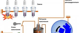
The system includes spark plugs, four high-voltage wires (one for each spark plug), a Hall sensor, a distributor, an ignition coil and, in fact, a switch.
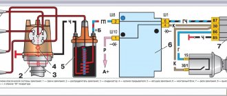
Rice. 1 Ignition circuit of VAZ 2109 Schematic illustration.
The ignition system generates an electrical impulse (spark), thereby igniting the mixture of fuel and air in the combustion chambers necessary for engine operation.
The switch is responsible for the cyclic supply of pulses to the ignition coil, this is necessary for the proper operation of the entire system as a whole.
Thus, if the switch is faulty, the spark will supply intermittently or be completely absent. It is not possible to drive such a car.
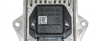
The VAZ 2109 switch itself consists of an aluminum case and a microcircuit installed on it. The device is mounted in the engine compartment and connected by wires to the ignition coil.
Rice. 2 Appearance of the VAZ 2109 switch.
The design of the housing and the mounting method allow the switch to successfully withstand vibrations that occur when the car is moving.
The VAZ 2109 contactless ignition system switch has the following performance characteristics:
- Voltage range 6–16 Volts.
- Operating voltage 13.5 Volts.
- Switching current 7.5–8.5 Amperes.
- A switch in good condition ensures an uninterrupted supply of spark to the cylinders with a crankshaft speed of up to 7000 rpm.
What could the ignition system switch look like?
The above switch circuit is just one of the options for how the ignition device can be implemented. This is done using:
- transistors;
- thyristors:
- hybrid elements;
- contactless sensors.
The transistor circuit of the switch is discussed above; the thyristor circuit uses energy accumulation in the capacitor, and not in the electromagnetic field of the ignition coil. During operation of the thyristor system, when control signals are received, the circuit connects a charged capacitor to the windings of the coil, through which it is discharged, causing a spark to appear. Without touching on the advantages and disadvantages that this or that circuit has, suffice it to say that any such device provides a significant improvement in all parameters of the ignition system, and the switch over time has replaced conventional battery ignition.
However, it is necessary to note one more stage in the development of the system, and the switch in particular. The use of electronic components and the introduction of a switch into the design of the car made it possible over time to abandon the contact voltage breaker and replace it with a contactless sensor. Such a system, in domestic cars, was first used in VAZ cars, in particular the VAZ 2108. A similar operating principle, when the switch receives signals from a special unit, is implemented on the VAZ 2108 using a Hall sensor.
When considering the options for what the switch device could be, one cannot ignore the development of the ignition system itself. The main principle that is implemented during its construction is increasing the reliability and efficiency of the entire system
This is achieved by using microprocessor systems that use the readings of numerous sensors. To work with such systems, you need at least a two-channel switch, and recently a separate coil and switch for each spark plug. This approach – a two-channel switch (later also multi-channel) allows you to provide:
- more powerful spark;
- elimination of losses in the distributor;
- stable idle;
- improved starting at low temperatures;
- reduction in fuel consumption.
It is worth noting that a two-channel switch allows you to get rid of the slider.
Signs of a broken switch
During the operation of the car, unpleasant symptoms may occur, indicating a malfunction of the ignition system.
A possible reason for this may be incorrect operation of the switch. Here are the most common symptoms that should suggest a possible breakdown of this device:
- Can't start the engine. There is no spark when the starter is running.
- The engine starts and runs normally at low and medium speeds, but cannot be revved up at high speeds. The engine is not running at full power.
- The car stalls when moving away, although it idles stable.
- The engine starts, but does not run for a long time and immediately stalls.
- The engine begins to operate unstably - “triple”, reaching a certain speed level. When cold it can start quite normally.
- The engine may periodically, without any pattern, stall, then work normally again. The battery discharge indicator lights up. The tachometer needle shows sharp changes in the number of revolutions.
Verifying switch operation
Every car enthusiast with a sufficient level of desire and minimal technical skills can check the operation of the switch.
The easiest way to check is to replace the unit with a new one that is known to be good. If after this the problems in the engine operation have disappeared, then we can conclude that the old switch has already served its purpose.
Every car enthusiast can replace the switch independently. First of all, you need to find it under the hood of the car.
The switch is located in the area of the left (driver's) pillar. It is connected by wires to the coil.
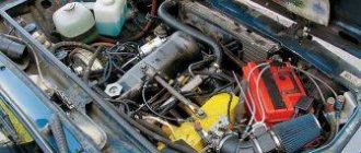
Rice. 3 Engine and organization of the engine compartment of the VAZ 2109.
1 – front glass of the shock-absorbing strut; 2 – water tank; 3 – air filter; 4 – fuel pump; 5 – steering rack; 6 – camshaft sensor; 7 – vacuum brake booster device; 8 – master cylinder of the brake system and its barrel; 9 – switch; 10 – fuses; 11 – engine cooling system tank; 12 – battery; 13 – hood fastening; 14 – ignition coil; 15 – starter; 16 – high-voltage wires; 17 – neck for oil; 18 – engine; 19 – candles; 20 – windshield washer system.
Next, disconnect the negative terminal from the battery. Then you should carefully disconnect the plastic bracket with wires from the switch. To do this, you need to release the spring clip.
Replacement
To make your own repairs, you need to be prepared. It is recommended to use a well-lit garage, and to dismantle the parts you will need a simple set of tools: a marker, a 10 mm wrench, a Phillips and flathead screwdriver. We will consider an example of replacing the hall sensor on a VAZ 2109 with dismantling the distributor. The step-by-step process is as follows:
- Secure the vehicle in gear or with the handbrake.
- Disconnect the negative terminal on the battery.
- Disconnect the high-voltage wires, marking with a marker which one was located.
- Remove the vacuum regulator hose.
- Disconnect the power supply from the hall sensor.
- Unscrew the top nut securing the distributor and wire bracket.
- Unscrew the bottom and rear mounting nuts.
- Use a marker to mark the location of the distributor so that you can install it back without unnecessary displacement and without adjusting the ignition timing.
- Move the distributor to the right along the studs.
- Take it to a well-lit workbench.
- Unscrew the screws of the ignition distributor cover and remove it.
- Remove the slider and plastic boot.
- Unscrew the plug screw.
- Remove the screws of the support plate.
- Remove the vacuum corrector (2 screws).
- Take out the block and wires.
- Remove the support plate with the sensor.
- Unscrew the two mounting screws on the DH and remove it.
- Install a new sensor.
- Collect everything in reverse chronology.
Other ways to test your switch
Despite the relatively low cost of a new switch, car enthusiasts do not always have the desire, and sometimes even the opportunity, to purchase it.
And even if the old switch is in good working order, replacing it will in no way affect the operation of the engine.
This is why many owners of VAZ 2109 cars prefer to check the old switch before replacing it with a new one.
Rice. 4 Mounting the switch on the car body.
This unit can be professionally checked at a service station using a specialized stand.
Professional equipment can show not only the presence or absence of an impulse from the switch to the ignition coil, but also their cyclicity and stability.
But not all service stations have such equipment, so craftsmen have come up with another simple way to check the switch.
For this test you will need an 8 wrench and a 12 V 3 Watt test light. The procedure is as follows:
- Remove the negative terminal from the battery.
- Using a size 8 wrench, disconnect the brown wire from the terminal marked “K” on the coil, which goes to the terminal marked “1” of the switch.
- Connect one end of the 12 V test lamp contact to this wire, and the other to the terminal marked “K” on the coil. Thus, the test lamp should be in the circuit between the coil and the ignition switch.
- Put the battery terminal back on.
- Try starting the engine. While the starter is rotating, the warning light should be on. If this does not happen, then the switch is not working and needs to be replaced.
You may be interested in:
Schematic electrical diagrams, connecting devices and pinouts of connectors
Today we will look at the design and diagrams of ignition systems for VAZ cars of all major models. Since carburetor versions of VAZ are practically history, we will dwell in detail on the ignition systems of injection cars. Their ignition system is based on an electronic ignition module. We also recommend that you carefully consider the choice of spark plugs and the quality of high-voltage wires, because the quality of the spark and, accordingly, the operation of the ignition system as a whole will depend on them. The information is intended as a reference guide for self-repairing a car.
How to determine if the ignition switch is faulty
The introduction of an ignition switch into the design of a car, especially on domestic cars of the VAZ family, made it possible to increase their reliability. And although the first production car with an electronic ignition system was the VAZ 2108, similar devices began to be installed on many other cars, primarily classics. However, the use of such a rather complex product has led to the fact that finding a malfunction, as well as checking and repairing the switch, has become possible for the most part only in specialized centers. External signs indicating that a malfunction has occurred may include:
- the engine does not start, there is no spark at the spark plugs;
- the engine starts but stalls after a few minutes;
- The motor is unstable; if the switch is replaced with a known good one, the defect is eliminated.
The easiest way to identify a malfunction and test a switch, as already noted, is to install a known-good one. Due to the rather low quality of the switches supplied for the VAZ family of cars, including the VAZ 2108, drivers have to carry additional switches with them to replace the failed one. However, there is also an indirect evaluation principle that allows you to check the performance of the product and identify its malfunction.
To do this, you can use the readings of the voltmeter in the instrument cluster. You need to turn on the ignition, and the needle will be in the middle of the scale, and a little later it will swing to the right (due to the power supply to the coil being turned off when the engine is not running). This arrow behavior indicates that there is no fault in the switch. In the event that there is no voltmeter, a test lamp is required to check the ignition. One end of it is connected to ground, the other to the output of the coil connected to terminal 1 of the switch. If you turn on the ignition, then if the switch is working properly, after a while the lamp will burn brighter.
However, in some cases, the ignition malfunction is not related to a switch failure. It is necessary to check the condition of the wires, first of all, contact with ground and the condition of the connectors. It is also necessary to check the Hall sensor.
The appearance of a voltage switch in the design of a car, including the domestic VAZ 2108, was a natural result of the development of the ignition system. Its further improvement was the use of first dual-channel and then multi-channel switches to improve operating efficiency.
VAZ-classic, switch check.mp4
Rate the usefulness of the article!
- Why do brake pads squeak when braking and what to do about it
- Replacing engine mounts on VAZ and other cars
- Car rental: what you need to know when choosing
- What does the braking distance depend on and what formula can it be calculated by?
- How well do you understand car emblems?
- How to remove the outer CV joint and replace a torn boot
- How to independently replace the internal grenade on VAZ cars
- Wheels for rotating the car in place 360 degrees
- In 3 years, diesel engines will become a luxury
- Review of the most expensive Hyundai Solaris ever
- Test drive Lamborghini Huracan from Mikhail Petrovsky
Pinout and diagram of the VAZ ignition coil
Pinout of ignition coil modules for various car models of the VAZ family:
Ignition VAZ 2101
1 – generator; 2 – ignition switch; 3 – ignition distributor; 4 – breaker cam; 5 – spark plugs; 6 – ignition coil; 7 – battery.
Ignition VAZ 2106
1 – ignition switch; 2 – fuse and relay block; 3 – EPHH control unit; 4 – generator; 5 – solenoid valve; 6 – microswitch; 7 – spark plugs; 8 – ignition distributor; 9 – ignition coil; 10 – battery.
Ignition VAZ 2108, 2109
Ignition VAZ 2110
Ignition VAZ 2111
Ignition VAZ 2112
Ignition VAZ 2114
Diagram of a non-contact ignition system: 1 – non-contact sensor; 2 – ignition distributor sensor; 3 – spark plugs; 4 – switch; 5 – ignition coil; 6 – mounting block; 7 – ignition relay; 8 – ignition switch.
How to check the sensor
To find out the condition of the sensor, you need to check the element. There are several ways to do this. Let's look at them:
- The simplest option is to install a known-good device, which you can borrow, for example, from a friend in the garage. If the problem disappears during the check and the engine starts working without interruptions, you will have to go to the store to purchase a new sensor.
Video: checking the sensor with a multimeter
Checking the Hall sensor on a VAZ 2107 can be done without the device. In this case, the sequence of actions will be as follows:
- We unscrew the spark plug on one of the cylinders or use a spare one and connect it to the high-voltage wire from the ignition coil.
- We connect the spark plug thread to the body mass.
- We remove the sensor, connect the connector from the switch and turn on the ignition.
- We hold it with a metal object, for example, a screwdriver, near the sensor. If a spark appears on the spark plug, then the device being tested is operational.
Connecting and replacing VAZ short circuit
The procedure for removing and installing the ignition coil on old VAZ models:
- First, disconnect the central high-voltage wire leading to the distributor (ignition distributor).
- Disconnect all power wires from the coil contacts. Since they are fastened with nuts, you will need an 8 wrench for this.
- If you don’t know which wires to connect to which connector later, it’s better to immediately remember or mark them somehow, so that later during installation you can connect them correctly.
- Unscrew the coil housing. It is attached to a clamp (clamp), which is pressed to the car body with two nuts.
- After the work has been done, you can remove the ignition coil and replace it if necessary.
For new type VAZ cars:
- We remove the “minus terminal” from the battery.
- Remove the top protective cover of the engine. If the engine volume is 1.5 liters, then this part is missing and this step is skipped.
- We remove the high-voltage wires from the coil.
- Now, using a 13mm wrench, unscrew the two fasteners.
- Using a 17mm wrench, loosen one bolt securing the coil.
- We take out the module.
- Use a hexagon to unscrew the coil from the holder.
- Assembly is carried out in reverse order.
Particular attention should be paid to the connection, since high-voltage wires must be located in the strict order provided for by the design. If this is not done, the car will stall or the engine may not start at all.
Replacing the ignition coil on a VAZ is quite simple. Even a novice motorist can do this in his garage, and if everything seems too complicated, contact a car service center. Particular attention should be paid to the choice of product, since this will determine how well the engine and ignition system will work.
What is the switch on VAZ 2108 cars?
This element in the operation of a car is an electronic unit that, receiving signals from a special magnetic induction sensor (also known as a Hall sensor), controls the operation of the ignition system. The schematic diagram of the device will not particularly worry us, because if the switch breaks down, it is simply replaced with a new one; it is much more important to understand how it works and, most importantly, how to diagnose it if necessary. But first things first.
The VAZ 2108 switch is connected directly to the ignition key, through which it is powered from the vehicle electrical network. The operating diagram of the device also assumes a direct electrical connection with the ignition coil and the spark plug distributor. The task of the automobile switch is to regulate the operation of automobile spark plugs through the ignition distributor using control signals from the sensor.
VAZ models 8 and 16 valves
Despite the similarity in engine design, the ignition system of the 1.5-liter injection 16-valve engine differs from the 1.6 16-valve engine. The 1.6 liter engine uses an electronic contactless ignition system with individual coils on each spark plug. Therefore, there was no need for an ignition module. Such a system is more reliable and cheaper to operate, since if one coil fails, there is no need to replace the entire module.
The 16-valve 1.5-liter VAZ 2112 injection engine used the same non-contact ignition system as the 8-valve engine, but a different ignition module was installed. Its catalog number is 2112-3705010. The design of the module remains the same - two ignition coils (for cylinders 1-4 and 2-3) plus switch keys in a single block. The spark is supplied to the cylinders in pairs using the idle spark method. This means that sparking occurs in two cylinders simultaneously - in one on the compression stroke (working spark), in the second on the exhaust stroke (idle spark).
Basic Switch Elements
The switch circuit is quite simple, but making this unit yourself is pointless, since buying a ready-made version will be much easier. Installation must be carried out as competently as possible, otherwise the device will not operate correctly. In addition, when using transistors, you need to carefully select them according to their parameters, and for this you need to have high-quality measuring equipment. Unfortunately, for two identical semiconductors, the spread of characteristics can be very large. And this affects the operation of the device.
The VAZ switch, designated 76.3734, consists of one main element - the L497 controller. It is designed specifically for use in contactless ignition systems. The domestic analogue of this controller is KR1055HP2. Their parameters are almost identical, which allows you to use any of the controllers. In addition, this chip allows you to connect a tachometer located on the dashboard of the car. But you can also use a simpler circuit, which is an amplifier unit of two stages. True, the reliability of such a device is much lower.
Video on repairing KZ VAZ
Every owner of the VAZ 2109 should know the ignition circuit Without knowing this circuit, you will not be able to start the car in case of ignition problems. Moreover, this scheme is elementary simple. The VAZ 2109 is equipped with a contactless ignition system. It consists of the following components: switch, ignition coil, distributor, Hall sensor, high-voltage wires and spark plugs. The task of the ignition system is to provide a timely, cyclic spark to the engine cylinders. Let's take a closer look at how the clamping circuit works.
Ignition circuit for VAZ 2109
ignition of the VAZ 2109: power is supplied to the ignition system through a relay. Until the key is in the ignition position, the relay will not turn on and supply power to the circuit. As soon as the key is turned, the ignition system is energized. +12V power from the battery is supplied to contact B of the ignition coil, the 4th contact of the switch. The Hall sensor powers the switch itself. Please note that the ignition relay is powered through the mounting block, and if there is poor contact in connectors Ш1, Ш8 or for some reason the track oxidizes or burns out, the ignition system will not be powered and the VAZ 2109 will not start. In order for a spark to begin to form, you need to crank the engine crankshaft. Together with it, the camshaft will turn and the Hall sensor will send an impulse to the switch. The commutator, in turn, will connect contact K of the ignition coil to ground, resulting in a spark appearing on the central wire. When the distributor slider connects the central wire and the wire leading to a specific engine cylinder, a spark will jump on the spark plug, igniting the combustible mixture. The engine will start. When it is necessary to turn off the engine, the driver, by turning the key in the ignition switch, turns off the relay, which in turn disassembles the power supply to the system. The switch and ignition coil become de-energized and stop working. The most common malfunctions of the VAZ 2109 ignition system: 1) Failure of the switch. 2) Failure of the Hall sensor. 3) Poor contact of the slider in the distributor. 4) Lack of power supply to the ignition system of the VAZ 2109. Go to Home.
What is BSZ and how does it work?
To successfully install and configure contactless ignition, it is advisable to understand the operating principle of the system, which consists of the following elements:
- Main ignition distributor (otherwise known as distributor). Inside it is installed a photoelectric Hall sensor, a vacuum drive for adjusting the advance angle and a so-called slider with a moving contact.
- A coil that produces a high voltage pulse. It has 2 windings: a primary winding, consisting of a small number of turns of thick wire, and a secondary winding, wound with a thin wire with a large number of turns.
- The electronic unit is a switch equipped with an aluminum cooling radiator. The latter plays the role of a fastening element.
- Spark plugs connected by high-voltage wires to the distributor.
- Wires for connecting elements to each other.
Scheme of operation of the BZS VAZ 2107
The first contact of the coil is connected through the ignition switch relay to the generator, and the second to the control unit. Also, a high-voltage wire with a large cross-section goes from it to the distributor. There are 2 bundles of wires coming out of the distributor, connecting it to the switch and spark plugs. The system operates according to the following algorithm:
- After turning on the ignition by turning the key in the lock, a voltage of 12 V is applied to the primary winding of the coil, which creates an electromagnetic field.
- When the crankshaft rotates and one of the pistons reaches top dead center (TDC), the photoelectric sensor sends a signal to the switch, which briefly breaks the connection between the coil and the voltage source - the generator or battery.
- During a circuit break, a voltage pulse of 20 to 24 kV is generated in the secondary winding of the coil, transmitted through a large cross-section wire to the distributor slider.
- The movable contact of the slider directs the impulse to the spark plug where the piston reached TDC. A powerful spark jumps between its contacts, igniting the mixture of fuel and air in the combustion chamber.
- The distributor shaft is driven by a gear transmission connected to the crankshaft. When the next piston moves to TDC, the shaft rotates and the moving contact connects to another spark plug, and the Hall sensor sends the next signal and the sparking cycle is repeated.
