What is ISO?
A little theory: the pinout of the ISO connector of the radio is determined by the functionality of the contacts in the plugs, in accordance with their numbering. ISO radio connector is a connector for connecting a car's standard radio, certified according to international standards.
Each of these connectors is designed as an eight-pin rectangular plug, but sometimes they are combined into one housing.
When trying to independently replace, for example, a car player from Pioneer with a JVC, car owners are faced with a situation where the wires in the plug are mixed up or do not even fit the shape of the connectors. In order to solve this issue, you need to buy an ISO plug, which is sold at any auto parts store. After that, pinout the head unit connector according to the diagram.
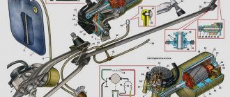
Pinouts for various brands of cars and radios
The wiring of the linear outputs on the standard radio depends on the make of the car and the head unit.
Before pinouting the connectors of the car radio, you must read the information presented on the cover of the device and in the instructions for it.
Toyota
For a standard plug: 1 - A+, 2 - GND, 3 - BAT+, 4 - backlight, 5 - antenna adjustment, 9-16 - speakers (RR+, RR-, RF+, RF-, LF+, LF-, LR+, LR -).
Universal connector for most models: 1 - ANT, 3 - linear output LR, 4 - GND linear outputs, 5 - linear output RR, 6 - CD in LCH, 7 - CD in GND, 8 - CD in RCH, 9 - CD reset , 10 — CD clock out, 11 — CD DSPL select, 12 — CD data out, 13 — CD clock in, 14 — CD data in, 16 — A+, 17 — GND, 18 — ANT GND, 22-27 and 29- 30 — speakers (LF-, LR+, RF-, RR+, LF+, LR-, RF+, RR-), 28 — CD mute, 31 — ANT CONT, 32 — CD ACC CONT, 33 — AMP CONT, 34 — B UP .
Nissan
Standard circuit: 1-6 - speakers (LR+, RR+, LR-, RR-, LF+, RF+), 7 - A+, 8 - backlight, 9 - BAT+, 10 - LF- speaker, 11 - RF- speaker, 12 - antenna control, 13 - GND.
Honda
Standard connector: 1 - RR+ speaker, 2 - LR+ speaker, 3 - backlight, 4 - BAT+, 5 - A+, 6 - antenna control, 7-10 - speakers (LF+, RF+, RR-, LR-), 13 - GND , 14-15 - speakers (LF-, RF-).
Universal connectors: 1 - A+, 2 - BAT+, 3 - GND, 4 - empty, 5-12 - speakers (RR+, RR-, LF+, LF-, RF+, RF-, LR+, LR-).
Alpine
Alpine TDE-7823W: 1 - BAT+, 2-5 - speakers (LR-, LR+, RR-, RR+), 7 - amplifier control, 8 - antenna adjustment, 9 - GND, 10-13 - speakers (LF-, LF+ , RF-, RF+), 16 - A+.
Alpine 7190M: 2 - amplifier control, 8 - GND linear outputs, 9-10 linear outputs (R, L), 13 - antenna, 27-28 - speakers (LR+, LR- and LF-, LF+), 29 - GND, 31 - BAT+, 32 - A+, 34-36 - speakers (RR+, RR- and RF-, RF+).
Mitsubishi
For all models: 1-2 — speakers (RR+, LR+), 3 — antenna, 4 — backlight+, 5-8 — speakers (LF+, RF+, RR-, LR-), 10 — A+, 11- BAT+, 12 — backlight, 13-14 — speakers (LF-, RF-), GND — connector rim.
Kenwood KDC KRC
There are several options for pinout of the radio chip from this manufacturer, depending on the model of the device:
- KDC5040R and others: 1 - GND, 2 - A+, 3 - antenna, 5-8 - speakers (RF+, RF-, LF-, LF+), 9 - BAT+, 10 - backlight, 11 - TEL mute, 12 - EXT AMPL CONT, 13-16 - speakers (RR+, RR-, LR-, LR+).
- KRC155D: 1 - GND, 3 - A+, 5 - BAT+, 8-9 - speakers.
- KDC84R and others: 1 - input A, 2 - GND input A, 7-10 - linear outputs (L, R, R, L), 11 - input A, 17-20 - GND linear output (L, R, R , L), 25 - GND, 26 - A+, 27 - amplifier, 33 - BAT+, 34 - backlight.
- KRC752R: 1 - ANT GND, 4 and 28 - output L, 5, 18, 27 and 39 - GND outputs (L, R, L, R, respectively), 8 - backlight, 9 - BAT, 10-13 - speakers (LR -, LR+, LF+, LF-), 14 — ANT, 17 and 40 — output R, 20 — antenna, 21 — A+, 22 — GND, 23-26 — speakers (RR-, RR+, RF+, RF-), 36 and 48 - phone interface.
Standard connection diagrams
Markings and types of connectors
Today, all car radio connectors comply with the ISO standard, and two connectors are used. Each is a plug with eight pins, sometimes the manufacturer can combine them into a single housing. Energy consumption sources are connected to one of them; it is marked with the letter A. As for the second, acoustics, that is, speakers, are connected to it. The connector designation is marked with the letter B.
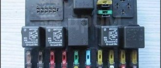
Adapters for car radio connectors
Head units with three outputs can be found on sale, but they are rare and usually represent an exception.
Even if the connected sockets do not correspond to each other, the car owner has several connection options:
- You buy a special adapter for the radio, which can be connected to the outputs of the speaker system.
- The second method is considered “collective farm” among car enthusiasts. Its essence is to cut off the non-standard output and wind the necessary wires to it. But we do not recommend using this option, because eventually the wires will begin to unwind, so the “collective farm” procedure will have to be repeated. In addition, the cost of adapters is not so high to use this method.
Standards 1DIN and 2DIN
All car radios can be divided into two types, which are installed by car manufacturers.
- 1DIN standard (single block);
- 2DIN standard (two-block).
Cars of European brands prefer 1DIN.
| №1 | Empty |
| №2 | Empty |
| №3 | Empty |
| №4 | Constant power |
| №5 | Antenna power |
| №6 | Backlight |
| №7 | Ignition |
| №8 | Weight |
And Japanese, American and a number of Chinese car brands use the 2DIN standard.
| №1 | Rear right "+" | Purple, "B1" |
| №2 | Rear right "-" | Purple black, “B2” |
| №3 | Front right "+" | Gray, "B3" |
| №4 | Front left "-" | Grey-black, "B4" |
| №5 | Front left "+" | White, "B5" |
| №6 | Front left "-" | White-black, "B6" |
| №7 | Rear left "+" | Green, "B7" |
| №8 | Rear left "-" | Green-black, "B8" |
Useful: Pinout of VAZ air flow sensor. Checking and repairing the air flow sensor
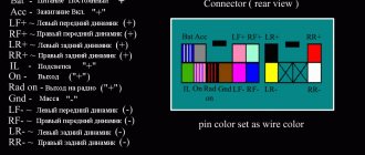
Connector B Diagram - Audio
| Contact number | Wire color | Purpose |
| B1 | Violet | Right rear speaker (+) |
| B2 | Purple-black | Right rear speaker (-) |
| B3 | Grey | Right front speaker (+) |
| B4 | Gray-black | Right front speaker (-) |
| B5 | White | Left front speaker (+) |
| B6 | White black | Left front speaker (-) |
| B7 | Green | Left rear speaker (+) |
| B8 | Green-black | Left rear speaker (-) |
Pinout diagrams for ISO connectors for Pioneer radios
The model name of the Pioneer car radio, the connection diagrams of which are shown above, can be found out from the file name of each diagram.
Remember: when connecting the device for the first time, you first need to supply power to the radio, and if it lights up and switches as expected, connect the speakers. Otherwise, you can burn not only your audio player, but also your expensive car speakers.
Connector A - Radio power supply
| Contact number | Wire color | Purpose |
| A1 | Any | Depending on the functions of the radio. Basically, this contact is used to control the volume of the radio depending on the speed of the car: The higher the speed, the louder the sound. |
| A2 (MUTE) | Any | Also, the purpose of the contact depends on the manufacturer and the available functions. Mainly used to mute music when there is an incoming phone call. |
| A3 | Any | Depending on the functions of the radio. |
| A4 | Yellow | Constant 12 Volt power supply. Needed to save the radio settings and remember the last song before turning it off on a USB drive. |
| A5 (ANT, REM) | Blue | Power to antenna, subwoofer or amplifier. It is needed so that the antenna, amplifier or subwoofer turns on only when the radio or radio is turned on. To avoid consuming battery power when the ignition is off. It is worth remembering that this contact is low-current, that is, it cannot connect many consumers. Otherwise, the power key may burn out and the radio will need to be repaired. |
| A6 (ILLUM) | Orange | Radio backlight. The power for this wire is taken from the wire of the instrument illumination lamp, buttons and other elements of the instrument panel, which are turned on by the side lights. |
| A7 (ACC) | Red | Power supply “12 Volt” from the ignition switch. Needed to turn on the device. When this wire is connected to the ignition switch, the radio will only work after the ignition is turned on. If the wire is connected together with the yellow one from pin A4 (that is, the power supply is constant), the radio will be able to work even without turning on the ignition, but there is a possibility that battery consumption will occur and overnight the battery will be discharged so much that there will not be enough energy for starter rotation. Therefore, it is necessary to “connect” the wire to constant power carefully, or do not forget to turn off the radio. |
| A8 (GND) | Black | Weight. Connect the negative wire. |
How to properly connect to an electronic device
The concept of an interface as we know it today dates back to the 1960s. More precisely, in 1964, when the company developed its legendary IBM System/360 mainframe. It was then that the main tasks of any interface - physical or virtual - were formulated. They were to provide a standard connection for all devices.
Euro connectors
Initially, only a few types of standard inputs could be made to ensure compatibility between products from different manufacturers. This was a PS/2 port for the keyboard, an LPT port for the printer, and a connector for the PCI card. Nowadays, each type of connection has its own standard interface; this approach greatly simplifies the development and sale of any type of device and allows you to understand their built-in capabilities. Here are descriptions of the main communication elements, first of all, the designation of the button on the radio, which are used on the panels of Pioneer and other car radios.
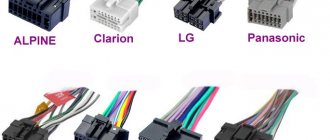
Types of branded connectors
Description of the buttons on the front panel of the radio for control (decoding)
| Button labels | Button function |
| A.F. | Different RDS frequency, automatic search when reception is poor |
| ALL OFF | Everything is off |
| AMS | Music sensor, works on the principle of playing a number of tracks equal to the number of clicks |
| ANG | Panel adjustment |
| ATA | The radio turns on automatically when you turn off and rewind media tracks |
| A.T.T. | Quickly reduces volume |
| BAND | Selecting a radio receiver |
| BEER | Enabling sound when pressing buttons |
| Blank Skip | Skips pauses longer than 8 seconds |
| BMS | Compensates for low frequencies when dropped due to the main device |
| BTM | Remembers the quality frequency of strong stations |
| CLK ADJ | Adjusts time |
| COLOR | Color |
| DISP | Display activation |
| DNPP | Selecting a CD in the changer |
| DNPS | Entering disc names |
| DSP | Activating the sound processor |
| EJECT | Remove the cassette from the cassette receiver or disc |
| EON | Reception of traffic information |
| FUNCTION | Switches the most used functions |
| INTO SCAN | Plays the recording for 10 seconds to search |
| LOS | Looks for stations, skipping with weak reception |
| LOUD | Tone compensation |
| M.RDM | Disc random playback |
| P.I. | Automatic search |
| PI SOUND | Switching to another frequency |
| PI MUTE | Muffled sound |
| POWER | Shutdown |
| PS | Listening to saved settings |
| PTY | Selecting a genre |
| RDS | Search for a station by metadata |
| RDM | Play disc tracks in any order |
| REG | Switching to the frequency of a radio station with RDS |
| Repeat Play | Replaying a track |
| SCAN | Scanning tracks and playing the beginning |
| SEL | Settings |
| SHUFFLE PLAY | Play available music in random order |
| SYSTEM Q | Tracking sound enhancement factors and showing them on the display |
| TA SEEK | Searching for a station with RDS |
| TC | Calling the tuner when rewinding |
general information
Do-it-yourself repair of Chinese pioneer car radios
AMP is a technology for accelerated mobile pages, which is developed by independent developers and actively promoted by Google in its search engine. Yandex has not yet joined this initiative, but I am sure that soon they will either implement this standard or come up with something similar in operating principle.
The bottom line is that the site uses special tags, the number and functionality of which are strictly limited. The developer's task is to assemble a hodgepodge of available schemes that will solve the customer's problem.
Pages with AMP rank higher than other queries in search due to the fact that they meet the requirements for fast loading and are adapted for mobile devices.
In fact, all such pages are static or conditionally dynamic, since they allow the use of form submissions, as well as iframes.
Next, I’ll tell you about the main features of AMP.
Connecting a car radio if there is an ISQ connector
The general standardization of recent decades is not such a bad thing. If you have a relatively new car, it most likely has a block near the “seat” for the car radio for connecting it. It is made according to the ISQ standard and connected to the car’s electrical/audio system. In this case, connecting the car radio is the simplest - connect two connectors and everything should work. True, you need to know which connector on the car to install the adapter in, but this should be in the description of the car... Or you can try to understand it by the inscriptions next to the sockets.
The car radio should include an adapter for the ISQ Euro connector.
If the car radio does not have such an output, then it needs an adapter from the standard connector to ISO. More or less serious manufacturers make such a connector or there is an adapter included with the radio. If you don’t have it, you can buy it or you will have to look for it exactly for your brand/model of radio, which is problematic.
ISO connector
It is much easier to purchase an adapter and, guided by the colors and pattern given on the cover, hook up the radio.
Pinout of the ISQ Euro connector for connecting a car radio
You can, of course, connect the radio without a plug. It is enough to understand the terminals on it and connect (or stretch the wires to the speakers) without confusing the plus and minus of the speakers with the amplifier outputs. However, using a chip simplifies the connection when you need to replace the radio.
Features of ISO adapters and connectors
The discrepancy between the shape and size of both the ISO output jack on the car player and the adapter plug from the standard car electrical system can hardly be called technical features. Rather, it is a problem and an extra headache for the motorist. The fact is that many manufacturers of audio equipment, as well as car manufacturers, supply their equipment with individually shaped Euro connectors.
Moreover, on different models of the same company, these sockets may differ from each other. But this can be called a global practice. A prime example of this is the discrepancy between chargers between brands and models of cell phones. Moreover, the cost of an ISO adapter for a radio is by no means small. The average price of a good quality device is about 500-600 rubles. Manufacturers are pleased, but what about car owners? There is only one thing that calms me down. Buying an ISO adapter for a Pioneer radio (Sony, JVC, etc.) is not difficult. We will tell you in more detail about some of the features of connecting the ISO adapter for the radio to Ford Focus 2 cars (Cadillac, Chevrolet Aveo T250, Toyota, Renault).
Accelerating Code: Tiles and Barriers
You can gain additional acceleration by using tiling. Tiling divides the threads into equal rectangular subsets or tiles. You determine the appropriate tile size based on your data set and the algorithm that you are coding. For each thread, you have access to the global location of a data element relative to the whole or and access to the local location relative to the tile. Using the local index value simplifies your code because you don't have to write the code to translate index values from global to local. To use tiling, call the on the compute domain in the method, and use a tiled_index object in the lambda expression.
In typical applications, the elements in a tile are related in some way, and the code has to access and keep track of values across the tile. Use the tile_static Keyword keyword and the to accomplish this. A variable that has the tile_static keyword has a scope across an entire tile, and an instance of the variable is created for each tile. You must handle synchronization of tile-thread access to the variable. The stops execution of the current thread until all the threads in the tile have reached the call to . So you can accumulate values across the tile by using tile_static variables. Then you can finish any computations that require access to all the values.
The following diagram represents a two-dimensional array of sampling data that is arranged in tiles.
The following code example uses the sampling data from the previous diagram. The code replaces each value in the tile by the average of the values in the tile.
Completion of work
Next, we move on to connecting the radio with the second part of the block. First, you need to find a diagram of the radio socket in the operating instructions or on the Internet. The correct pinout of the radio block is very important.
According to this diagram, we connect the wires by color, be sure to insulate them and, without putting the radio in place, check that all speakers are turned on and sound. Do not forget to connect the separately located antenna wire connector, the radio tuner will not work.
If you fail to turn on the radio the first time, check all the wire connections again and check the supply voltage. After eliminating the errors, check the activation again.
If everything is turned on, working and radio broadcasting stations are received, you can install the radio in its original place. Enjoy the new sound of your car!
Shaping and Indexing Data: index and extent
You must define the data values and declare the shape of the data before you can run the kernel code. All data is defined to be an array (rectangular), and you can define the array to have any rank (number of dimensions). The data can be any size in any of the dimensions.
index Class
The index Class specifies a location in the or object by encapsulating the offset from the origin in each dimension into one object. When you access a location in the array, you pass an object to the indexing operator, , instead of a list of integer indexes. You can access the elements in each dimension by using the or the .
The following example creates a one-dimensional index that specifies the third element in a one-dimensional object. The index is used to print the third element in the object. The output is 3.
The following example creates a two-dimensional index that specifies the element where the row = 1 and the column = 2 in a two-dimensional object. The first parameter in the constructor is the row component, and the second parameter is the column component. The output is 6.
The following example creates a three-dimensional index that specifies the element where the depth = 0, the row = 1, and the column = 3 in a three-dimensional object. Notice that the first parameter is the depth component, the second parameter is the row component, and the third parameter is the column component. The output is 8.
extent Class
The extent Class specifies the length of the data in each dimension of the or object. You can create an extent and use it to create an or object. You can also retrieve the extent of an existing or object. The following example prints the length of the extent in each dimension of an object.
The following example creates an object that has the same dimensions as the object in the previous example, but this example uses an object instead of using explicit parameters in the constructor.
Pinout
Explaining in accessible language which color wire is responsible for which function in the device. The pinout can be presented as:
- graphic diagram;
- tables.
Description in free form. It is this form of representation of the pinout of car players from Pioneer (Prology 1715t), Sony, Kenwood, Hyundai, JVC, Mystery) that we will use in this information article.
ISO connector is a contact technical device for connecting electrical wires along their groups of eight contacts (16), in two or one rectangular housing.
The brown block connects the wiring for the speaker system and sometimes its control (control of changing radio stations or musical compositions from the steering wheel of a car).
Black block - power (electrical) supply of contacts between the car and the sound-reproducing device.
Sometimes the contacts are combined in one connector, and they are separated into groups in the upper and lower parts of a single housing. ISO is a generally accepted technical standard for goods and services developed by an international organization for standardization.
ACC is a connection that allows you to listen to music and radio without starting the car.
Markings and types of connectors
Today, all car radio connectors comply with the ISO standard, and two connectors are used. Each is a plug with eight pins, sometimes the manufacturer can combine them into a single housing. Energy consumption sources are connected to one of them; it is marked with the letter A. As for the second, acoustics, that is, speakers, are connected to it. The connector designation is marked with the letter B.
Head units with three outputs can be found on sale, but they are rare and usually represent an exception.
Even if the connected sockets do not correspond to each other, the car owner has several connection options:
- You buy a special adapter for the radio, which can be connected to the outputs of the speaker system.
- The second method is considered “collective farm” among car enthusiasts. Its essence is to cut off the non-standard output and wind the necessary wires to it. But we do not recommend using this option, because eventually the wires will begin to unwind, so the “collective farm” procedure will have to be repeated. In addition, the cost of adapters is not so high to use this method.
Euro and ISO sockets and working with them
Experts call power connectors not chips, but sockets. This term comes from electronics and refers to the connection location. The pinout is also a way to connect an electronic device to the vehicle's on-board system. At the same time, the layout of the radio chip may differ for cars, for example, Toyota, Mitsubishi or Volvo, as well as for model brands - Sony, Pioneer, JVC and others.
EURO ISO car radio connector
Please note that adapters for the Euro connector are available for all car radios; this helps to avoid problems with pinout and allows you to unify and protect the “native” connections from damage when disconnected. It is these connectors that are usually called chips, although the term allows for a much broader interpretation. The Euro connector is also classified as an ISO connector.
Chips (connectors, adapters, adapters) for connecting radios
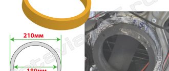
Installing a radio
Standard devices do not always satisfy the requirements of users, so they are replaced with radios selected to suit their taste.
Car radio installation
Previously, installing a radio caused quite a lot of problems, due to the fact that each manufacturer, be it the expensive Pioneer or the cheap Saundmax, used their own connection standards, and you had to cut into the car wiring diagram to install the connector. Recently, there has been standardization in this process; many manufacturers are introducing the so-called euro feature.
Radio socket
That is, you need to connect the mating part to the car circuit once and then simply remove the radio tape recorder and install another one. If you purchased a fairly “new” car, then this connector may have already been installed by the manufacturer. if it is not there, then it’s okay, the work of installing it is not particularly difficult, you can do without the services of an auto electrician, spending a couple of hours and doing everything yourself.
Car radio connectors
Sound settings
In order for the radio to play juicily and reproduce low frequencies well, you need to adjust the equalizer curve and adjust the cutoff of low or high frequencies. The equipment supports adjusting the sound balance between speakers; there is a separate function for dynamic bass boost (BASS BOOST).
The sound quality is affected by the bitrate of audio recordings stored on laser discs or removable storage devices. If the recording quality is low, it is impossible to correct the sound picture using the settings.
Equalizer
Equalizer curves with standard parameters are stored in memory; to select the required value, use the menu (EQ Settings subsection). Radio tape recorders support creating your own sound picture by recording parameters in a separate memory cell.
High and low pass filter subwoofer
Setting up the slice is done through the menu, where you need to find the Crossover parameter. The function is supported only by some equipment; the setting algorithm depends on the modification of the acoustic device. Some models allow you to set individual characteristics for each speaker. The cutting height is selected from the list of suggested values.